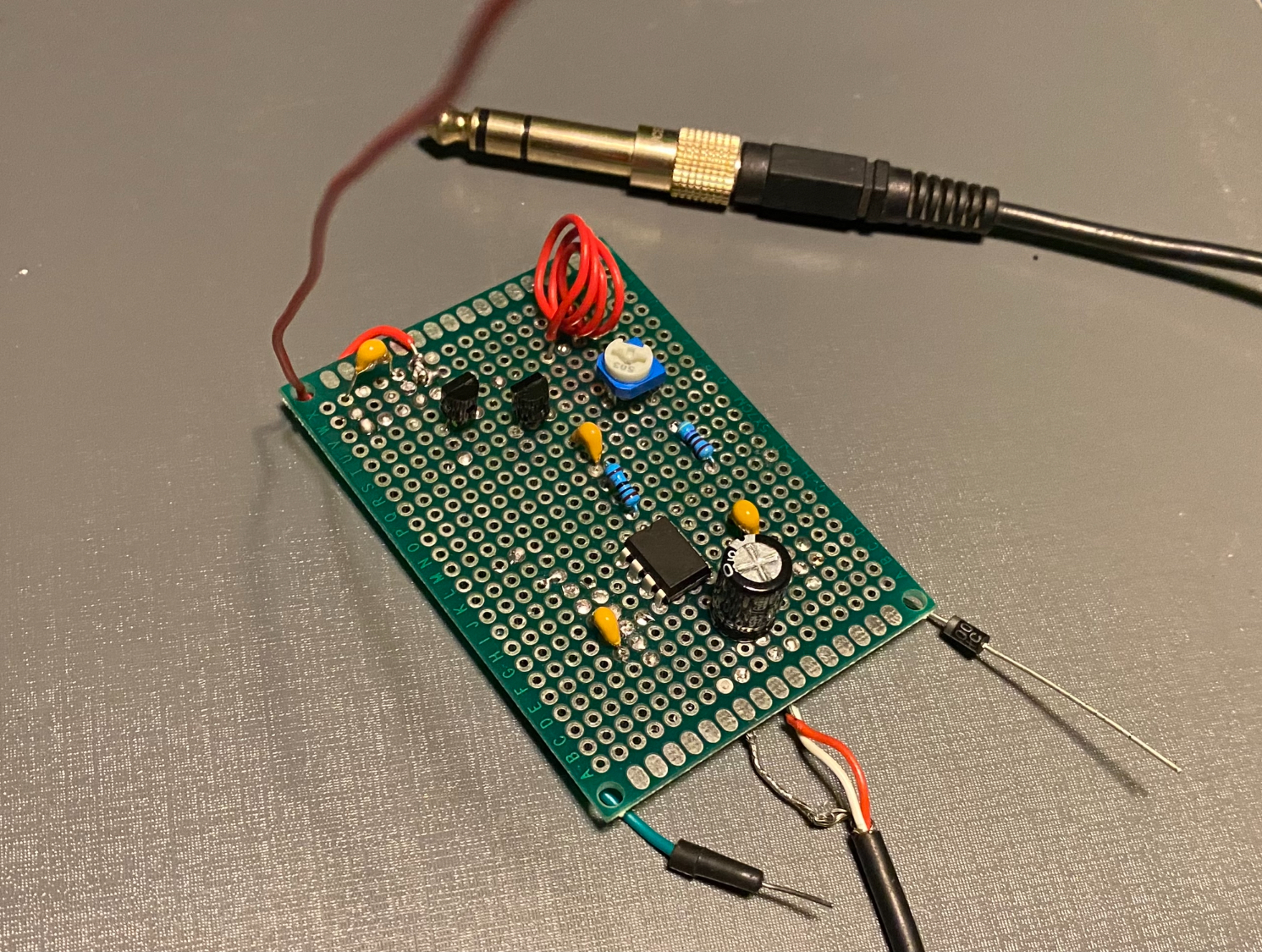
This project is a radio receiver using a variable inductor as a tuner.
I was interested in making this device because I wanted to learn more about radio waves since it is such a large part of our day-to-day life. I also wanted a project that expanded my abilities.
I already knew how to solder and have completed many other basic electronics projects. The only thing I had yet to do, that I felt would truly be beneficial, was something involving radio waves. I thought it would be a great fit for this assignment.
For the receiver to work, it requires (3) components: the oscillator, the amp, and the carrier subtractor. The oscillator is an LC circuit (inductor and capacitor) where the electrical current changes direction between the capacitor and inductor at a particular frequency. That frequency is the station number that you dial when you tune into a radio station.
Radio waves are a combination of two waves. One is the carrier wave, the other is the audio wave. These two waves are combined during broadcast by a modulator, therefore the combining of the two waves is called modulation. Once the wave reaches the antenna of the receiver, the carrier wave is inverted and cancelled out by a modulator on the receiving end. This process produces a pure audio signal. Modulation can be with something as simple as a single transistor. The resulting pure audio signal is very quiet, therefore an amplifier is required in order to hear it.
To accomplish these (3) aspects in a single circuit: Oscillator, Subtractor, and Amplification, I used an already designed circuit and modified a few things. The main thing I modified was the LC oscillator circuit. Originally it used a variable capacitor and a fixed 0.15 Microhenry inductor. I replaced this with a fixed 10 Picofarad capacitor and made a variable inductor. For me, this ended up being more doable. Weather it be a: Variable capacitor with a fixed inductor or a Fixed capacitor with a variable inductor, both options are viable. What's key is the relationship between the inductance and capacitance. To maintain a frequency with a higher capacitance you need a lower inductance and vice versa. The formula for inductance is based on many variables. One of these variables is coil length.
The way I made the variable inductor is by crafting a basic inductor and compressing the coil to change the inductance. I used a guitar amplifier to boost the signal so that it's audible.
I learned a lot during the making of this project. The whole process entails exactly how each section of the circuit worked for me. I had to sift multiple iteration and different versions to find one that works. I expressed enough understanding to be able to modify the circuit and make everything work. This process has increased my knowledge greatly on radio wave transmission and reception. I plan on implementing these concepts in future projects that require wireless communication. I’m excited by the possibilities.
:)